Product Highlights
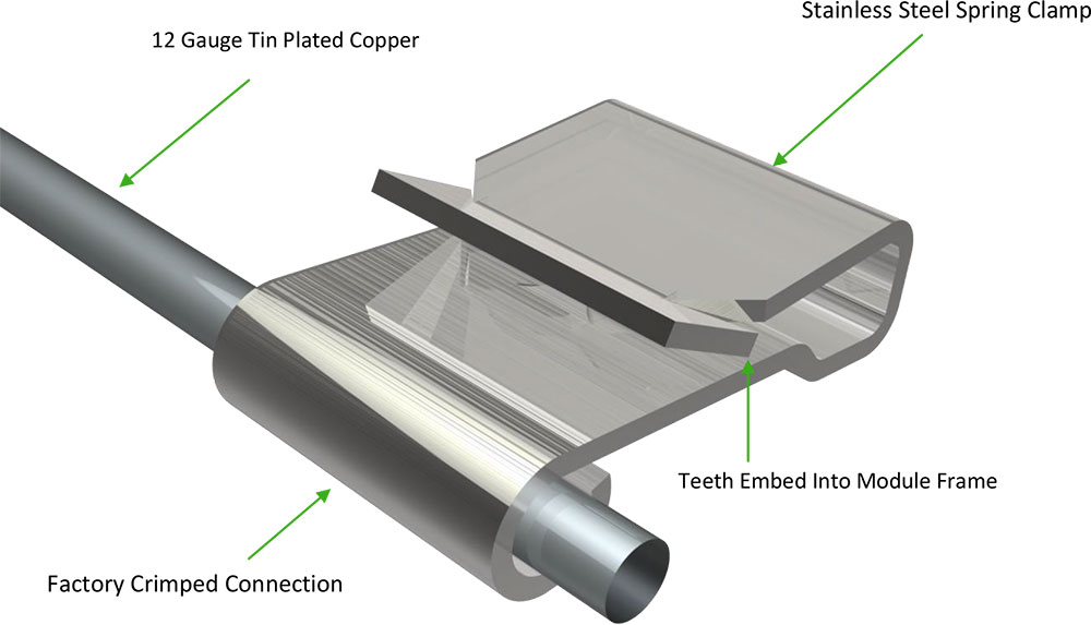
- 12 gauge tin-plated copper
- Stainless steel spring clamp
- Factory crimped connection
- 8″ (204mm)
- 12″ (304 mm)
- 38″ (965mm)
- 50″ (1270mm)
- 76″ (1930mm)
- 96″ (2438mm)
Installation
The following information is provided as a general guideline on how DynoBond is installed for grounding photovoltaic (PV) solar modules. For more information, technical questions and other inquiries, contact DynoBond using the convenient page on this web site. Click Here.
Jump to pitched roof installation
Jump to flat roof installation
Pitched Roof Installation
Step 1
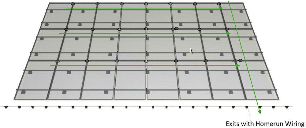
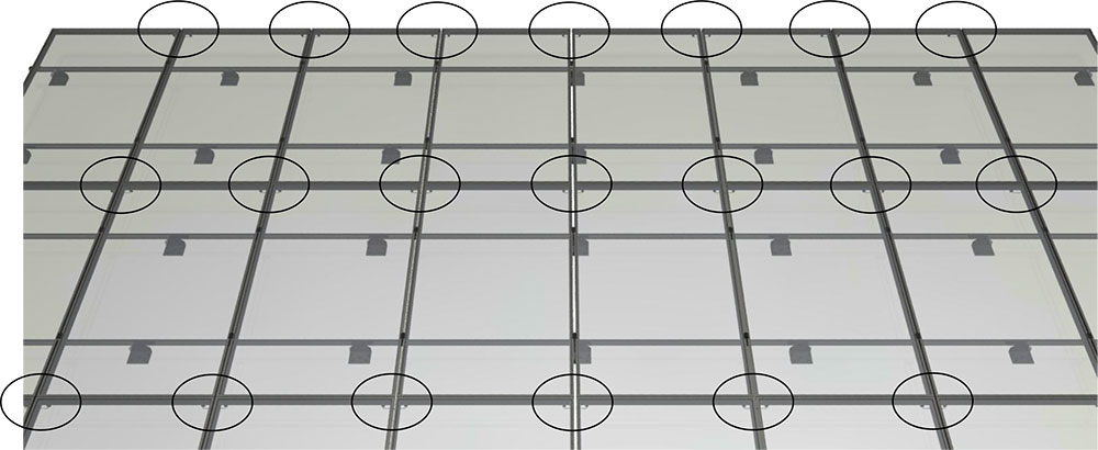
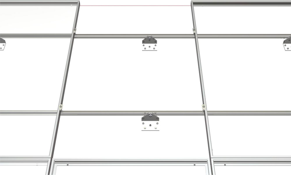
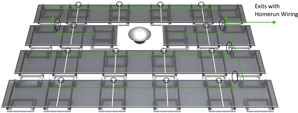
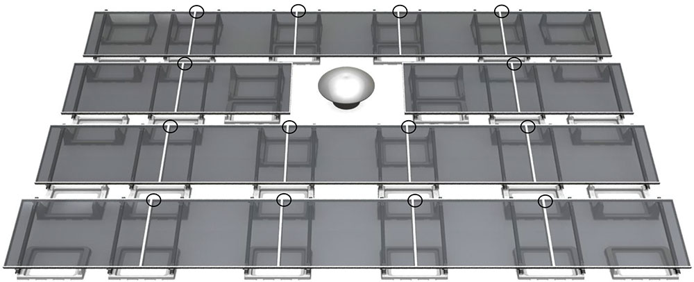
Begin by charting your installation. In this example, the system consists of 3 rows of 8 modules per row totaling 24 modules shown in portrait. DynoBond is installed in the same manner for pitched roof systems mounted in landscape. The homerun wires are shown exiting the system at the southeast corner of the array. DynoBond will be installed to connect the modules west to east across each individual row. DynoBond will also be connected on a row to row basis from North to South to bridge each row together. DynoBond is used as a jumper between modules. The highlighted circles are the location of DynoBonds for this specific installation. DynoBond can be installed while installing the modules or if space permits after the module installation is completed.
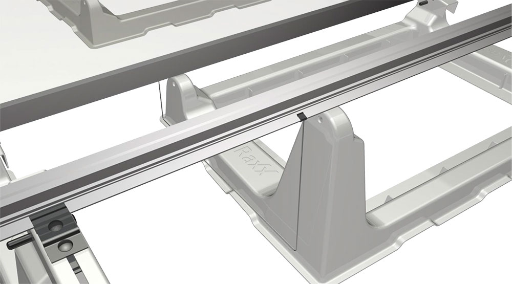
Locate DynoBond between the first set of modules. DynoBond penetrates the anodized coating of the modules’ frames bonding them together. DynoBond is used as a jumper between modules acting as a bridge for the equipment ground path. The connection points can be made along either the short or long sides of the panels granted the frame is the same on all four sides of the module.
A. Short Side Connection
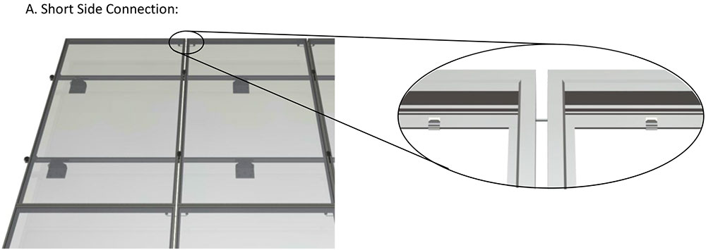
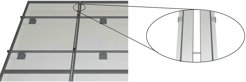
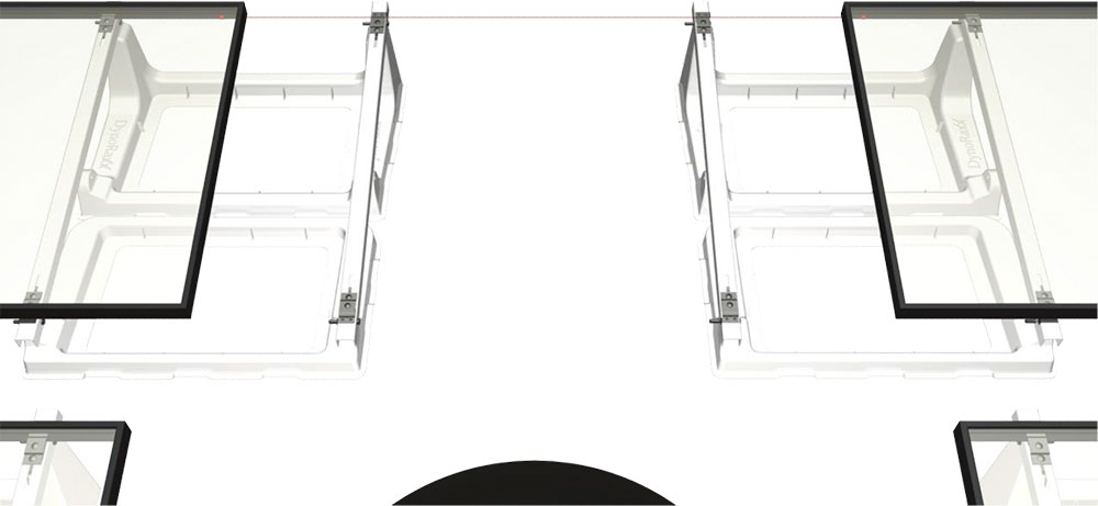
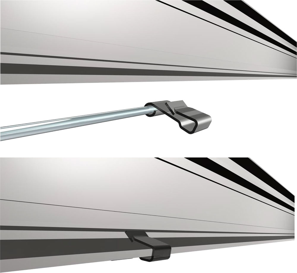
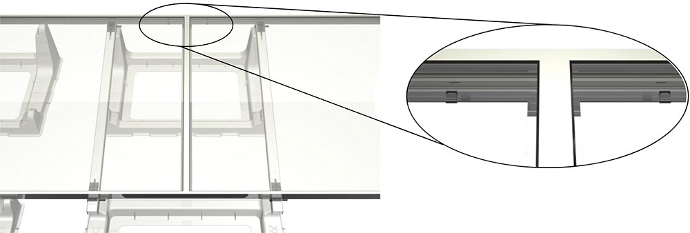
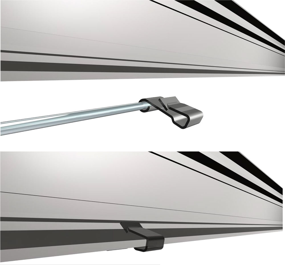
Position DynoBond on the bottom lip flange of the first module. To engage the module frame fit the module’s bottom lip flange between the toothed section of the stainless steel spring clamp. Next, fit the adjacent module with the free end of DynoBond. Leave slack in wire for expansion and contraction of module frame.
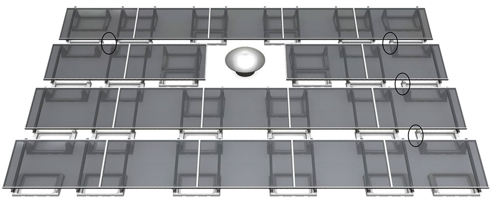
Continue connections between modules across each individual row. This is shown in the below diagram circled in black.
DynoBond is able to follow the array layout on any installation. After the modules have been bridged across the row it is time to connect each row together. One DynoBond is needed to connect one row to the next. The connection does not need to be in a straight column. It can be staggered following the contours of the installation. The only requirement is that all rows are interconnected together by at least one point. Please see diagram below for an example of staggered inter row bridging. Connection points are highlighted with black circles.
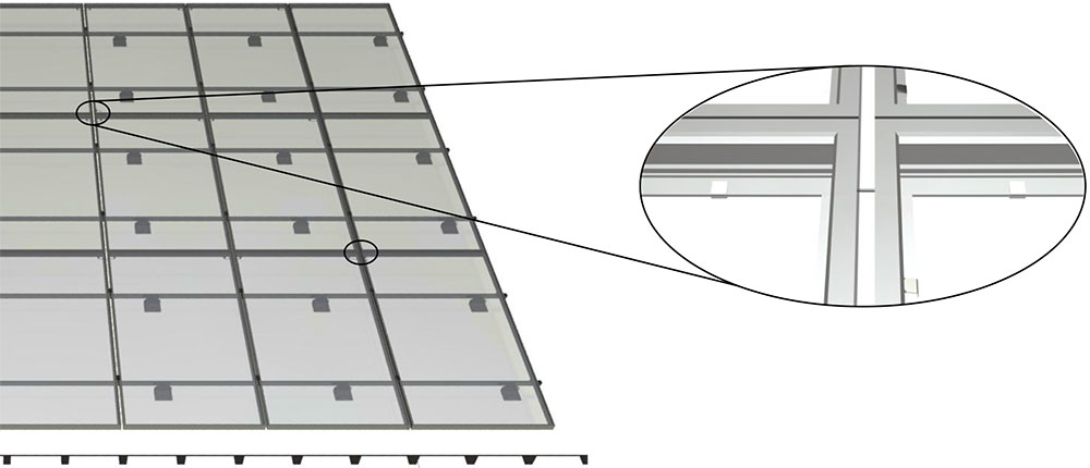
The homerun equipment ground wire can be landed via a grounding lug attached to a grounding point of a module anywhere throughout the array. Please keep in mind if a panel is removed within the array at any point for maintenance or service a DynoBond should be placed to maintain ground continuity. This replacement DynoBond is highlighted in red for clarity.
Flat Roof Installation
Step 1
Begin by charting your installation. In this example, the system consists of 4 rows of 4 and 5 modules per row totaling 19 modules. In this instance, the homerun wires are exiting the system at the northeast corner of the array. DynoBond will be installed to connect the modules west to east across each individual row. DynoBond will also be connected on a row to row basis from North to South to bridge each row together. DynoBond is used as a jumper between modules. The highlighted circles are the location of DynoBond Assemblies for this specific installation. The DynoBond can be installed while installing the modules or if space permits after the module installation is completed.
Locate DynoBond between your first set of modules. DynoBond penetrates the anodized coating of the modules’ frames; bonding them together. DynoBond is used as a jumper between modules acting as a bridge for the equipment ground path. The connection points can be made along either the short or long sides of the panels granted the frame is the same on all four sides of the module.
A. Long Side of Module
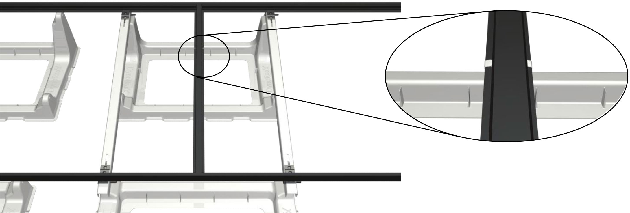
Position DynoBond on the bottom lip flange of the first module. To engage the module frame fit the module’s bottom lip flange between the toothed section of the stainless steel spring clamp. Next, fit the adjacent module with the remaining free end of DynoBond. Leave slack in wire for expansion and contraction of module frame.
Continue connections between modules across each individual row. This is shown in the diagram below circled in black.
DynoBond is able to follow the array layout on any installation. After the modules have been bridged across the row it is time to connect each row together. One DynoBond is needed to connect one row to the next. The connection does not need to be in a straight column. It can be staggered following the contours of the installation. The only requirement is that all sections of an array are interconnected together by at least one point. Please see diagram below for an example of staggered inter row bridging. Connection points are highlighted with black circles.
The homerun equipment ground wire can be landed via a grounding lug attached to a grounding point of a module anywhere throughout the array. Please keep in mind if a panel is removed within the array at any point for maintenance or service a DynoBond should be placed to maintain ground continuity. Highlighted in red for clarity.